

")
Publication History
Submitted: October 16, 2023
Accepted: October 23, 2023
Published: December 11, 2023
Identification
D-0173
Citation
Md. Faisal (2023). Water Washing System to Reduce Exhaust Odor of DI Diesel Engines at Idling. Dinkum Journal of Natural & Scientific Innovations, 2(12):852-869.
Copyright
© 2023 DJNSI. All rights reserved
852-869
Water Washing System to Reduce Exhaust Odor of DI Diesel Engines at IdlingOriginal Article
Md. Faisal 1*
- Rajshahi University of Engineering and Technology, Bangladesh; faisal.bdmail@gmail.com
* Correspondence: faisal.bdmail@gmail.com
Abstract: DI diesel engine vehicles are becoming popular because of their friendly behavior to the environment as it emits lower CO2. The main cause of it is that it consumes relatively smaller amount of fuel than a gasoline engine vehicle. The reduction of exhaust odor can be done mainly in three ways. One of them is to optimize the engine parameters. But researches have shown that the reduction of odor is not significant. Water washing of exhaust gases traps most of the odorous components like aldehydes, organic acids or other odorous gas components. The water-washing system can be applied at idling and at low temperature operation. Since the emission of exhaust odor at idling and at low temperature operation is higher than any other engine condition, and the exhaust gas temperature is much lower at idling and low speed operation, the water-washing system can be used. Some previous researches have shown that odor can be reduced greatly by washing the exhaust gas by water. Since there are no proper systems to reduce the exhaust odor at idling, this thesis report focuses on the water-washing system. In the water-washing system the exhaust was passed through water. From this experiment, by using proper system with test engine at no load condition we tried to reduce exhaust CO, NOx, PM and specially odorous component than without attachment. Our main target was to bring odor level below 2 which is not uncomfortable for human being. For this, we used three systems as water washing system such as water washing system with tank washing, water washing system with shower and water washing system with shower & water tank. By using above these systems we successfully reduced odor level. And CO, NOx & PM were also significantly reduced by water washing system with tank washing, water washing system with shower and water washing system with shower & water tank. A water tank was used for water washing system with water tank and water washing system with shower & water tank. We changed water height inside the water tank from 3 ft (0.9144 m) to 4.5 ft (1.3716 m) such as 3 ft (0.9144 m), 4 ft (1.2192 m) and 4.5 ft (1.3716 m). It was found from this experiment, NOx must increase with increasing height of water in the water tank. But odor, CO and PM were reduced with increasing height of water in the tank. From this experiment, it was found that no fuel panalty occur with water washing system with shower, water washing system with tank washing with 3 ft (0.9144 m) height of water and water washing system with shower & tank with 3 ft (0.9144 m) height of water.
Keywords: water washing system, odor, exhaust, diesel engine, Idling
- INTRODUCTION
Generally there are two types of road vehicles on the basis of fuel used – one is gasoline engine vehicle and the other is diesel engine vehicle. Also diesel engine is of two types – DI diesel engine and IDI diesel engine. In DI diesel engine, the total combustion occurs in the combustion chamber whereas in IDI diesel engine, the preliminary combustion occurs in a divided chamber and main combustion occurs in the main combustion chamber [1]. Recent researchers have focused their attention to CO2 emission, which has a significant share on green house effect. The emission of CO2 is directly proportional to the fuel consumption and is said to be responsible for future changes in world’s climate. Fuel consumption and CO2 emissions from DI diesel engines are 20-30% less than gasoline engines. This merit implies less impact on climate change as well as savings of energy resources. The unburnt hydrocarbon (UHC) and carbon monoxide (CO) emissions are also significantly lower in diesel engines than that of gasoline engines without a catalyst. Moreover, diesel engines have the best reliability and durability over other 1C engines. On the other hand the emission of particulate matters (PM), nitrogen oxides (NOx) and exhaust odor are higher in DI diesel engines than other 1C engines [2]. Most of the diesel engine researchers have focused their attention to reduce PM and NOx, because these are the regulated emissions. And for better marketability of diesel engines these emissions must be reduced below to the regulated limit. Although the exhaust odor is not regulated yet, in near future some of the strongly smelling components like aldehydes should be regulated for the safer environment and for the health concern of the human being, and already in USA, the formaldehyde (HCHO) is under regulation since 1998 [3]. Hence this research work focused the attention for the odor reduction in DI diesel engines. Uncontrolled emissions from heavy-duty diesel engines have a significant impact upon air quality. Odor reduction in DI diesel engine at idling is a challenging matter due to low gas temperature. The main objectives of this work are to observe the improvement of exhaust odor & other emissions for using water washing system with tank washing by varying hight of water inside water tank, to observe the exhaust odor & other emissions for using the water washing system with shower, to observe the exhaust odor & other emissions for using the water washing system with shower & water tank, and to observe what amount of fuel panalty occur for each of above three case comparing wthout system.
- LITERATURE REVIEW
The links between public objection and the intensity of the diesel exhaust odor have been more or less established [1, 2]. By the literature survey it is found that at the middle of the 70’s, exhaust odor attracted the eyes of the people as an exhaust emission problem with the diesel engine. When the vehicles with the DI diesel were increased, this problem became an emergence to all. Diesel engines belong to the group of CI engine of the IC engines. CI stands for compression ignition. Now-a-days the IC engines play a dominant role in the fields of power, propulsion, and energy [3]. According to the reference [4], the fuel injector has a significant influence on odor formation. Some experimental results indicate that the products of partial oxidation are the main cause of odor in the diesel exhaust. This partial oxidation may be because of either very lean mixture such as during idling or due to the quenching effect. A good correlation has been found between the flammability limits and the odor intensity of the diesel exhaust. This along with the nature of diesel air- fuel ratio distribution explains the mechanism of odor production [5]. In diesel combustion there are most probably regions in which the fuel/oxygen/inert mixture is outside the flammability limits. The fuels in these regions, which are too lean to burn, might only partially oxidize resulting in odorous products of incomplete combustion [5].
Barnes [6] has related the formation of odorant to the lean flammability limit of the fuel. The combustion of diesel in a diesel engine is well understood in general terms and can convenient be divided into two main regimes. In the first, fuel is injected into the cylinder for a finite time, the ignition delay, before ignition takes place. During this period, fuel is mixed with the air and the initial heat release occurs. The heat release rates are controlled by the chemical kinetics relevant to the local mixture ratios. After ignition, and after the consumption of the ready-mixed fuel and air, the combustion becomes controlled by the fuel-air-mixing process [1]. Ignition first takes place in fuel spray zones, which combine long residence times with equivalence ratio histories that maximize reaction rates. These zones are believed to be in the trailing edge of the fuel spray where fuel has fully vaporized and equivalence ratios are around 1. The reaction zone or flame propagates throughout the rest of the prepared mixtures and reaches temperatures in excess of 20000C. In very fuel lean regions, the concentration of fuel and ignition – intermediate molecules are so low that the reaction zone cannot propagate into them and ‘flame out’ occurs. This phenomenon is due to the low specific heat release caused by the presence of a large number of ‘inert’ molecules (excess oxygen, nitrogen and stable fuel molecules) leading to the reduced local temperatures and reaction rates [1]. The fuel molecules, which undergo slow degenerate chain branching reactions and appear in the exhaust as partially oxidized hydrocarbons, are the major odorants, which affect the lean flammability limits, should affect the exhaust yields of odorants [7]. Recently the emission researches of diesel engines are going on mostly for the regulated emissions such as NOx, PM, and others due to severe regulation standards of those components. Emission standards specify the maximum amount of pollutants allowed in the exhaust gases discharged from a diesel engine. The regulated diesel emissions include carbon monoxide (CO), nitrogen oxides (NOx), particulate matters (PM), and hydrocarbons (HC). Hydrocarbons are regulated either as total hydrocarbon (THC) emission, as non-methane hydrocarbons (NMHC), or aldehyde emissions. One combined limit for HC+NOx is sometimes used instead of two separate limits. Table 1 shows the Japanese emission standard for light-duty diesel engines. The regulated values of NOx and PM in 2002 are 20% and 40% tighter respectively, than the level in 1998. Application of diesel engines in confined spaces is regulated through occupational health and safety ambient air quality standards in addition to the tail pipe regulation [10].
Table 1: Japanese emission standards for light-duty diesel engines (Passenger cars and commercial vehicles)*[3]
| Year | NOx (g/km) | PM (g/km) | HC (g/km) | CO (g/km) |
| 1994 | 0.6 | 0.2 | 0.4 | 2.1 |
| 1998 | 0.4 | 0.08 | 0.4 | 2.1 |
| 2002 | 0.3 | 0.05 | 0.12 | 0.63 |
| 2005** | 0.15 | 0.014 | 0.024 | 0.63 |
*The test method is the 10-15 mode cycle. **www.dieselnet.com
The ambient air quality standards specify maximum concentrations of air contaminants, called permissible exposure limits (PEL) or threshold limit values (TLV) which are allowed in the workplace. Gases found in diesel emissions, including carbon monoxide (CO), carbon dioxide (CO2), nitric oxide (NO), nitrogen dioxide (NO2), sulphur dioxide (SO2) and many other components (e.g. aldehydes), have their PEL. Diesel particulate matters have also been listed by a growing number of occupational health and safety standards as a toxic air contaminant. Table 2 presents one regulation for underground mining. But no strict regulations are adopted yet for the non-regulated components such as intensive smelling aldehydes (except HCHO) and polyatomic hydrocarbons (PAH). But, some researches are still going on for the reduction of odorous emissions from diesel engines due to the health concern of the human being [10].
Table 2: Permissible exposure limit (PEL) for the major diesel exhaust emissions [3]
| Substance | PEL (ppm) | PEL (mg/m3) |
| CO | 25 to 50* | |
| CO2 | 5000 | |
| NO | 25 | |
| NO2 | 3 to 5* | |
| SO2 | 2 to 5* | |
| PM | – | 1.5 |
| HCHO | 0.5 |
* PEL of four countries- USA, Canada, Germany and South Africa are united.
Due to less CO2 emission and better fuel economy, the DI diesel engine vehicles are very popular. But it is found that the odor emission occurs largely at idling and at low temperature operation. It is known that at the idling of diesel engine it runs with lean mixture. Now, a better method of reducing the odor is one of the most important research sectors. At present various types of odor reduction methods are suggested. The most effective odor reduction method is fitment of minimum sac volume injectors in that large reductions of exhaust odorant concentrations are attainable with little or no deterioration in thermal efficiency or smoke [1]. Further reductions may be obtained by minimizing fuel dispersion during the ignition delay period. This can, in part, be realized by adopting fuel pumps with an injection timing plan set to give minimum ignition delay. An additional method is to reduce the air motion in the engine. However, the consequences of this course of action are reduced mixing rates and pre-mixed burning, which unfortunately result in high smoke level and reduced thermal efficiencies [4]. But recent researches have shown that the above-mentioned systems are not so accurate and can’t able to reduce the exhaust odor to a satisfactory level. By previous researches, it `was found that adjustments or modifications to engine parameters alone are not sufficient to reduce odor levels to acceptable limits. Also researches accomplished by alternate fuels have shown that odor cannot be reduced to a satisfactory level [3]. Catalytic method is only applicable when the vehicle is in running condition where the exhaust gas temperature is above 200° or so [3]. From the above discussion of odor reduction techniques it is found that, there are hardly any appropriate methods to reduce odor at low temperature condition. Hence this study focuses on odor reduction at low exhaust temperature condition at idling by a non-catalytic system. So, with this concern charcoal adsorption and water washing system are introduced though a number of researchers have already applied their effort with this regard. A research on optimization of charcoal-adsorbing system to reduce exhaust odor in DI diesel engines at idling is already performed. But the odor level was not reduced to a satisfactory level [11]. Another research has performed on charcoal-silica gel adsorber system, also odor was not reduced to a desired level but surprisingly result was better than the previous and researcher argued that the inclusion of alumina or silica gel aid the charcoal for increasing adsorbivity [12]. Soon after an additional treatment of exhaust gas was executed this was the combination of charcoal adsorption system and water washing system in series connection. This system minimizes odor level significantly to 2.85 but unfortunately this also was not sufficient enough that can create comfort to human being. So by analyzing the above fact we must come to the point that farther research must be required on the improvement of the charcoal adsorption system to reduce the odor to a satisfactory level. In the literatures on diesel odor research, there are many experiments attempting to reduce odor intensity by changing engine designs or operating parameters. It can be said general that the fuel injector design and combustion chamber shapes are the principal design parameters that influence the odor intensity. The best way to reduce odor is the minimization of unburned or partially burnt fuel. A catalytic device in the exhaust has been shown to be somewhat effective for odor control. Considerable researches were conducted to determine the effects of design and operating variables on diesel exhaust odor and to find ways to reduce the odor intensity. In term of published results, only moderate success has been achieved in the odor reduction objective. However, the residual odorous emissions are still at unacceptable levels and must be reduced further.
- MATERIALS AND METHODS
3.1 Experimental Setup
The following shows the schematic diagram for the experimental setup of the odor assessment system.The performers used three kind of system those are very useful for odor reduction as water washing system. Such as, water washes system with water tank or tank washing system, water washing system with shower, and water washing system with shower & water tank. In each case CO and NOx were measured by using gas analyser. But odor was measured by exposing nose. And, PM was not measured by recognised method. Dilution method is worldwide famous for measuring PM. But we measured PM by following way: At first we chose two similar size filter papers for each engine speed. Then we chose two similar shape boxes for these filter papers. Actually, each individual box contains single filter paper. Then we measured weight of these two boxes by electric balance & we wrote the measurement value. Then we attached these two filter papers with PM measuring system. After that we hold this at the tail end of the test engine or tail pipe of the system till 3 minutes. Then we took off this from tail pipe of the system or tail end of the test engine. Then we uncovered the filter papers from PM measuring system. Then we put the filter papers into the boxes. Then we measured the weight of these boxes with filter papers by electric balance & we wrote the measurement value. Then we subtracted this value & above value. By this way we got two different values for each individual box. Then we add these values & after that multiply with 1000. Finally, we got the required value in miligram per 3 minutes. We measured PM by following method (sample calculation):
We got, PM = 26 miligram/ 3 min = 8.67 miligram/ min for without attachment at 700 rpm at no load condition.
Now, PM = 8.67 miligram/ min ————————— ( i )
We know, volumetric efficency = Va / Vs ——————– ( ii )
Where, Va = 3.079 d2 √( h × H / T ) lb/min ——————– ( iii )
h = 5 sin 140 cm of water (For 700 rpm, h = 5 sin 140 cm of water
= 1.209 cm of water 500 rpm, h = 2.5 sin 140 cm of water
= 0.475 inch of water 900 rpm, h = 7.5 sin 140 cm of water)
H = 30 inch Hg
T = 298 K
d = bore dia. = 0.812 inch
Now, from (iii)
Va = 3.079 × (0.812)2 √ ( 0.475 × 30/298 ) lb / min
= 0.4439 lb / min
= 0.4439 / 2.2 kg / min
= 0.2017 kg / min
we know, Vs = Pa × Vd × N/2 ————————— ( iv )
where, Pa = 1.24 kg / m3
Vd = swept volume
= 553 cc
= 553×10-6 m3
N = Engine rpm
= 700 rpm
so from ( iv ),
Vs = 1.24 × 553×10-6 × 700/2
= 0.24 kg / min
Now, volumetric efficiency = 0.2017 / 0.24 ( From ( ii ) )
= 0.84
Now at 700 rpm amount of exhaust gas = Vd × volumetric efficency × N/2
= 553×10-6 × 0.84 × 700/2 = 0.162 m3 / min
Now, 0.162 m3 / min = 8.67 miligram / min
0.162 m3 = 8.67 miligram
1 m3 = 53 miligram
So, it is clear that in above case, 53 miligram PM are exhausted with per cubic meter exhaust gas.
3.1.1 Experimental Setup with Tank Washing System
The figure 1 shows tank washing system.There water tank & other attachment such as inlet & outlet pipe made by GP sheet. Because of lower cost, GP sheet was chosen by performers. From the fig: 2.1-1 it is clear that the tail pipe of the test engine is connected to inlet pipe of system. The exhaust unpurifird raw gas coming from test engine is passed through the inlet pipe into water tank.Then it is washed by fresh water. The exhaust gas is left through the outlet pipe from the tank and then purified washed gas passes to the atmosphere.Outlet pipe of the system is analyzed by gas analyzer and human sensing. In this system water height in the water varied from 3ft to 4.5ft such as 3ft, 4ft & 4.5ft. By variation of water height we got different result for each emissions like CO, NOx, PM & specially odor.
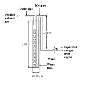
Figure 01: Tank washing system
3.1.2 Experimental Setup with Shower System
The Figure 2 shows water washing system with only shower. There tunnel & other attachment such as inlet & outlet pipe and vapour absorption system were used by authors. From the figure 2 we show that the tail pipe of the test engine is connected to inlet pipe of system. The exhaust unpurifird raw gas coming from test engine is passed through the inlet pipe into tunnel of the shaower system.Then it is washed by fresh water which falling from the shower. The exhaust gas is left through the outlet pipe to the vapour absorption system. In vapour absorption system, silica gel was used.Then purified washed gas passes to the atmosphere from the vapour absorption system.
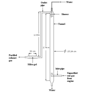
Figure 02: Water washing system with shower
3.1.3 Experimental Setup with Shower & Water Tank System
The following figure 3 shows water washing system with combination of shower & water tank. There tunnel, water tank, inlet pipe, outlet pipe vapour absorption system and shaower were used by authors. These made by GP sheet. Because of lower cost, GP sheet was chosen by performers.From the fig: 2.1-3 we show that the tail pipe of the test engine is connected to inlet pipe of system which is attached to the tank. The exhaust unpurifird raw gas coming from test engine is passed through the inlet pipe into water tank .Then it is washed by fresh water in the tank. Then the gas passes to the tunnel. Then the gas is re-washed by fresh water which falling from the shower. The exhaust gas is left through the outlet pipe to the vapour absorption system. In vapour absorption system, silica gel was used. Then purified washed gas passes to the atmosphere from the vapour absorption system. In this system water height in the water varied from 3ft to 4.5ft such as 3ft, 4ft & 4.5ft. By variation of water height we got different result for each emissions like CO, NOx, PM & specially odor.
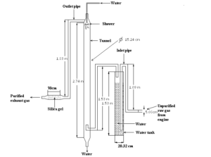
Figure 03: Water washing system with shower & water tank
3.1.4 TEST ENGINE AND FUEL
A four-stroke single cylinder DI diesel engine with specification as in table 1 was used for this research work. The study used diesel fuel. Table 1 shows the properties of the test fuel.
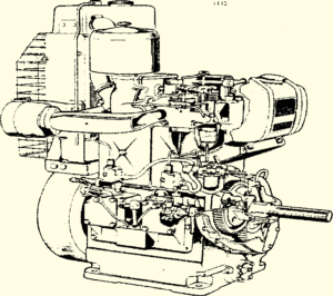
Figure 04: DI diesel engines (Peter Engine)
Table 3: Engine specifications
| Engine type | 4-stroke DI diesel engine |
| Number of cylinders | One |
| Bore x Stroke | 80 x 110 mm |
| Swept volume | 553 cc |
| Compression ratio | 16.5:1 |
| Rated power | 4.476Kw@1800 rpm |
| Fuel injection pressure | 14 MPa (at low speed, 900 to 1099 rpm)
20 MPa (at high speed, 1100 to 2000 rpm) |
| Fuel injection timing | 240 BTDC |
The properties of the fuel (diesel) that we used are given in the table 4.
Table 4: Properties of the test fuel (diesel)
| Fuel properties | Diesel fuel |
| Calorific value (kJ/kg) | 45540 |
| Density(at 320 C)ρ(gm/cc) | 0.84 |
| Viscosity(at 320C)μ(CP) | 4.3 |
| pH value(at 300C) | 5.63 |
| Flash point (0C) | 50 |
| Cetane No. | 50 |
| Carbon residue (gm/100gm) | <35 |
| Pour point (0C) | -32 |
| Cloud point (0C) | -16 |
3.1.5 System Designation
Table 5: Specification of water washing system
| Name | Water washing system |
| Material | GP sheet |
| Tunnel length | 2.74 m |
| Diameter of the tunnel | 15.24 cm |
| Water tank length | 1.53 m |
| Diameter of the water tank | 20 cm |
| Length of vapour absorption system | 30 cm |
| Size of the filter paper | 10 microns |
Design Criterion
Water was used for washing unpurified gas owing to availability by nature. GP sheet was selected for making inlet & outlet pipe due to lower cost, easy replacement and availability. No gas leakage. Silica gel was used in vapour absorption system.
3.3 Odor Assessment Method
An odor or odor is a volatilized chemical compound, generally at a very low concentration, which humans and other animals perceive by the sense of olfaction. Odors are also called smells, which can refer to both pleasant and unpleasant odors. Almost all researches in the field of odor research have used the human noses as the primary diesel exhaust odorant measurement technique [16, 17].Methodology for sampling and presentation to the ‘nose panel’ varies among researches. Some researches used instrumental methods to investigate the odorous components and to make a correlation between instrumental methods and human- sensing [18, 19]. No odor detection instrument has ever been developed which has the sensitivity and versatility of the human nose.
3.3.1 Human-sensing
In assessing odors, a group of test persons is exposed to dilute exhaust gases to determine the odor threshold, which is identified as the dilution ratio where odor is detected by 50% of the test persons. This odor threshold method does not include any evaluation of discomfort from exhaust gas and is time consuming. This study used an odor intensity scale to evaluate the discomfort level of the exhaust gases. The intensity scale and corresponding explanation of odor rating are given in table 1.4-1. a difference of one point has been reported as equivalent to a 10 fold change in the concentration of odorous gases [5]. So a 1 point improvement in the odor is a significant improvement. Deviations in the sensual assessments vary from person to person when the test personnel is in experienced, while reliable results can be obtained with experienced personnel [6].Thus the results obtained with a few experienced assessors are adequate for the assessments, and this study used three experienced assessors. Human sensing is one kind of organoleptic method where human nose is used, and is a subjective method of odor measurement. This study used and odor intensity scale to evaluate the discomfort level of undiluted exhaust gases. The odor scale was presented in table 1.5.There are two types of human sensing-one is direct assessment and the other is indirect assessment. In the human sensing, usually direct assessment is used at the exhaust manifold or at the tail pipe. In case of test of this study, the assessment was performed at the tail pipe. The assessors check the odor rating directly by exposing their nose to the exhaust stream at the tail pipe. Exposure time for odor checking is about 3 to 4 seconds.
3.3.2 Instrumental Assessment
It is stated earlier that the human-sensing method used the human nose for odor analysis and is a totally subjective measurement method of odor. However, it is highly desirable to eliminate the totally subjective odor measurement method. Consequently, several instrumental methods of analysis have been developed for the odor analysis. In the instrumental methods odorants that have been correlated with odor through the use of human odor panels are chemically determined, that means all instrumental methods depend on the human nose for final characterization and qualification of odor. Instrumental assessment can be done by HC Meter, GC-Analysis, HPLC-Analysis, and PH Method. The laboratory facilities do not permit to use the first three instrumental assessment methods. Hence pH method was used. A pH value of odorous components condensed in an aqueous solution is one indicator to evaluate the odor intensity of diesel exhaust. In reference [6], the pH measurement technique using a cold trap system is proposed and has been shown that there is a good correlation between the pH value and the odor rating as assessed by professional perfumers. It has also been shown that the odor rating decreases with the increase in pH values and vise versa [3]. The pH meter is a meter which is used to determine the pH value of a solution. A pH meter was used to determine the pH value of the condensed water. The specification of this meter is given bellow
Table 6: pH meter specification (MODEL 3051 pH METER)
| Range | 0-14.00pH |
| Resolution | 0.01pH |
| Accuracy | + 0.02pH |
| Temperature | Manual |
| Compensation | 0 to 1000C |
| Size | 150x60x26mm |
| Weight | 140gm |
| Battery | PP3/6F12/MN1604 |
Two buffer solutions (4pH and 7pH) and a beaker of distilled water was required. The electrode was immersed in 7 pH buffer. The display was set to read the value of the buffer solution as 7 (at the temperature of the °C control setting) by the BUFFER control. The electrode was then immersed in 4 pH buffer. The display was set to read the value of the buffer solution as 4 (at the temperature of the 0C control setting) by the SLOPE control. The electrode was rinsed in deionized water before each measurement. The electrode was immersed in the unknown solution or sample. The display was read directly in pH. The pH value of the aqueous solution of the exhaust gas is one indicator to evaluate the odor intensity. In reference [20], the pH measurement technique using a cold trap system at about -50°C is proposed. In another study, ph measurements by cold trap systems under various conditions were attempted [5]. The authors used the bag sampling method. The bag used to sample gas is of 15 liter volume and the sampling time is only about 5 seconds. Then 50 cc of pure water is poured in the bag to create a solution. The bag containing the sample solution condenses the odorous components by jerking the bag about one minute. After that the pH value is measured by a pH meter.
- RESULTS AND DISCUSSION
This system is complicated. This system is not feasible to use in diesel engine vehicle. This system can be used for stationary purpose.To use this system at first the engine speed was selected at which different tests were carried out. For this thesis 500 rpm, 700 rpm & 900 rpm engine speed was selected. CO, NOx, fuel consumption, back pressure and odor were measured after engine warm up. We took all data at the tail end of the test engine for getting good result & establishing proper comparison among water washing systems & without attachment at no load condition because of in that case engine temperature had low. In all following case data were taken after warm-up (8 minutes after warm-up). This experimental data based on various attachments. Those are using without system, using tank washing system with 3ft or 0.9144 m height of water in water tank, using tank washing system with 4ft or 1.2192 m height of water in water tank, using tank washing system with 4.5ft or 1.3716 m height of water in water tank, using water washing system with shower, using water washing system with shower & water tank with 3ft or 0.9144 m height of water in water tank, using water washing system with shower & water tank with 4ft or 1.2192 m height of water in water tank, and using water washing system with shower & water tank with 4.5ft or 1.3716 m height of water in water tank. To determine the exhaust odor and to make a comparison with pH value, two engine conditions as described to compare the results between with and without charcoal-absorber in the warm-up condition, data were taken during the warm-up condition at 700 rpm, from Ito 16 min, to compare the results between with and without charcoal-absorber at various rpm after the engine is warmed-up. The rpm was varied as 700, 900 and 1100. The Figure 5 shows the odor decreases with the increasing of the pH value and vise versa. However, a 1 point change in the pH value, causes only a 1 point change in the odor rating. Decrease in pH increases eye irritation and odor intensity. Figure 6 shows odor rating for tank washing system comparing without system. Water height in water tank was varied as 3ft(0.9144m), 4ft(1.2192m) and 4.5ft(1.3716m) height of water in tank. In every case fresh water was used in tank. In the moment of collecting data the engine conditions were after warm up (500 rpm, 700 rpm, 900 rpm) at no load.
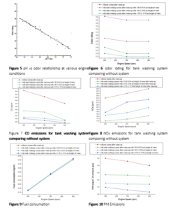
Figure 7 shows CO emissions for tank washing system comparing without system. Water height in water tank was varied as 3ft(0.9144m), 4ft(1.2192m) and 4.5ft(1.3716m) height of water in tank. In every case fresh water was used in tank. In the moment of collecting data the engine conditions were after warm up (500 rpm, 700 rpm, 900 rpm) at no load. The Figure 7 shows with increasing engine speed, CO emissions decreses gradually. Figure 8 shows NOx emissions for tank washing system comparing without system.Water height in water tank was varied as 3ft(0.9144m), 4ft(1.2192m) and 4.5ft(1.3716m) height of water in tank. In every case fresh water was used in tank. In the moment of collecting data the engine conditions were after warm up (500 rpm, 700 rpm, 900 rpm) at no load. Figure 9 shows amount of fuel consumed by test engine for using tank washing system with comparing without system. Water height in water tank was varied as 3ft(0.9144m), 4ft(1.2192m) and 4.5ft(1.3716m) height of water in tank. In every case fresh water was used in tank. In the moment of collecting data the engine conditions were after warm up (500 rpm, 700 rpm, 900 rpm) at no load. Figure 10 shows PM emissions for tank washing system comparing without system. Water height in water tank was varied as 3ft (0.9144m), 4ft (1.2192m) and 4.5ft (1.3716m) height of water in tank. In every case fresh water was used in tank. In the moment of collecting data the engine conditions were after warm up (500 rpm, 700 rpm, 900 rpm) at no load. The figure 10 shows with increasing engine speed, PM emission decreases. The figure 10 also shows, lower amount of PM were produced from engine using this system than without attachment. With increasing water height in tank, PM decreases. Figure 11 shows odor rating for water washing system with shower comparing without system. In the moment of collecting data the engine conditions were after warm up (500 rpm, 700 rpm, 900 rpm) at no load. The figure 11 shows odor was high at 500 rpm for both with & without attachment. And the figure 11 also shows using water washing system with shower, odor was reduced than without attachment. Figure 12 shows CO emissions for water washing system with shower comparing without system. In the moment of collecting data the engine conditions were after warm up (500 rpm, 700 rpm, 900 rpm) at no load. The figure 12 shows with increasing engine speed, CO were decreased for both with & without attachment and also shows using water washing system with shower; CO was significantly reduced than without attachment. Figure 13 shows NOx emissions for water washing system with shower comparing without system. In the moment of collecting data the engine conditions were after warm up (500 rpm, 700 rpm, 900 rpm) at no load. The figure 13 shows with increasing engine speed, NOx emission increases for both with shower system & without system. And also shows using water washing system with only shower, NOx was reduced than without attachment. Figure 14 shows fuel consumption for water washing system with shower comparing without system. In the moment of collecting data the engine conditions were after warm up (500 rpm, 700 rpm, 900 rpm) at no load. The figure 14 shows with increasing engine speed, the amount of fuel consumed by test engine was increased for both with shower system & without system. No difference was observed by performers between fuel consumption for without attachment & fuel consumption for water washing system with shower which is clearly shown in figure 14. Figure 15 shows PM emissions for water washing system with shower comparing without system. In the moment of collecting data the engine conditions were after warm up (500 rpm, 700rpm, 900 rpm) at no load. The figure 15 shows with increasing engine speed, PM emission decreases. From the figure 15, it is clear that lower amount of PM were produced from the engine by using this attachment than without attachment. Figure 16 shows odor for water washing system with shower & water tank comparing without system. Water height in water tank was varied as 3ft (0.9144m), 4ft(1.2192m) and 4.5ft(1.3716m) height of water in tank. In every case fresh water was used in tank.
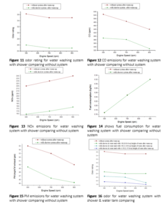
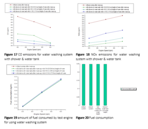
Figure 17 shows CO emissions for water washing system with shower & water tank comparing without system. Water height in water tank was varied as 3ft (0.9144m), 4ft (1.2192m) and 4.5ft (1.3716m) height of water in tank. In every case, fresh water was used in tank. In the moment of collecting data the engine conditions were after warm up (500 rpm, 700 rpm, 900 rpm) at no load. Figure 17 shows with increasing engine speed, CO emissions decreases gradually in any condition. Figure 18 shows NOx emissions for water washing system with shower & water tank comparing without system. Water height in water tank was varied as 3ft (0.9144m), 4ft(1.2192m) and 4.5ft(1.3716m) height of water in tank. In every case fresh water was used in tank. In the moment of collecting data the engine conditions were after warm up (500 rpm, 700rpm, 900 rpm) at no load. Figure 18 shows with increasing engine speed, NOx emission increases for both with shower & water tank system and without system. And the Figure 18 also shows with increasing height of water in water tank, NOx emissions increase gradually but this increasing rate must below the scale of NOx emissions at without attachment. Figure 19 shows amount of fuel consumed by test engine for using water washing system with shower & water tank comparing without system.
- CONCLUSION
The odor is reduced significantly with water-washing system. An electrochemical gas analyser was used to measure the NOx and CO emissions. The odor reduced significantly in these systems. The conclusion can be summarized as the water washing system with tank washing and with shower & water tank reduced CO, odor & NOx significantly. The reduction is almost proportional to the height of the water in the tank i,e the higher the water height, the higher the reduction and vice versa. Some back pressure developed in water washing system with tank washing and with shower & water tank. Back pressure did not create any influence on fuel consumption when 3 ft (0.9144 m) height of water was used in water tank in water washing system with tank washing and with shower & water tank. Water washing system with shower was enable to reduce exxhaust odor, NOx , CO. But it did not reduce odor below 2 . For this, water washing system with shower & water tank was used by performers to bring the odor level in below 2 which is not uncomfotable for human being. From this thesis, it has been determined that the oxides of nitrogen and CO are reduced significantly with water washing system (with shower, with tank washing and with shower & water tank) comparing without system. Water-washing system also reduces eye irritation. From the experimental result, eye irritation time for without attachment is 6-7second and with tank washing is 15-20 second and with shower & water tank is above 30 second.
REFERENCES
- Roy, M.M., Tsunemoto, H., and Ishitani, H., “Effects of Injection Timing and Fuel Properties on Exhaust Odor in DI Diesel Engines”, SAE International Spring Fuels and Lubricants Meeting and Exposition, Michigan, USA, May 3-6, (1999), Paper No. 1999-01-1531, SP-1462.
- Roy, M.M., “Reduction of Exhaust Odor and Eye Irritation in DI Diesel Engines”, A Thesis Paper of M. Sc. In Mechanical Engineering, Kitami Institute of Technology of Japan.
- Roy, M.M., “Exhaust Odor Reduction in DI Diesel Engines – Effects of Engine Parameter, Fuel Property and Oxidation Catalyst”, Ph. D. Thesis, Kitami Institute of Technology of Japan.
- Ingram, Colin, “Diesel Exhaust Odor of Small, High, Speed, Direct Injection Engines,” SAE Paper 780114, (1974).
- Tsunemoto, H., and Ishitani, H., and Roy, M.M., “Evaluation of Exhaust Odor in a Direct Injection Diesel Engine,” The International Conference on Internal Combustion Engines, Wuhan, China, October 22-24, (1997), p341-345.
- Tanaka, T., Kobashi, H., and Sami, H., “Development of a Diesel Odor Measurement method and its Application to Reduction,” SAE paper 920726, (1992).
- Shiozaki, T., Otani, T., Joko, I. and Ohnishi, T., “A Study of the White Smoke and the odor of DI Diesel Engines in a Cold Weather environment”, Proceedings of JSAE (in Japanese), Paper No. 912247(1991),p.3.57-3.60.
- Roy, M.M., Tsunemoto, H. Ishitani, H., Akiyama, J., Minami, T., and Noguchi, M., “Influence of Aldehyde and Hydrocarbon Components in the Exhaust on Exhaust odor in DI Diesel Engines”, SAE International fall fuels and Lubricants Meeting and Exposition, Baltimore, Maryland, USA, October 16-19, (2000), Paper No. 2000-01-2820, SP-1561.
- Tsunemoto, H. Ishitani, H. and Kudo, R., “Evaluation of Exhaust Odor in a Direct Injection Diesel Engine”, Transactions of the JSME, Vol. 62, No. 604, 1996, pp. 2543-260.
- Savery, C.W., Matula, R.A., and Asmus, T., “Progress in Diesel Odor Research”, SAE Paper No. 740213 presented at Detroit, February 1974.
- Azizur Rahaman and Moshiar.”Optimization of charcoal-absorbing system to reduce exhaust odor in DI diesel engines at idling” Thesis Paper 1997-1998..
- Fariqul Hasnat and MD.Hasib Reza.”Odor reduction by charcoal-silica gel adsober system in DI diesel engine at idling” Thesis Paper 1998-1999
- Henein, N. A., “Analysis of Pollutant Formation and Control and Fuel Economy in Diesel Engines”, Progress in Energy and Combustion science, Volume 1, 1975.
- Ford H. S., Merrion, D. F. and Hames, R. J., “Reducing Hydrocarbons and Odor in Diesel Exhaust by Fuel Injection design”, SAE Paper No.770734, 1970.
- Greeves, G. Khan, I. M., Wang, C. H. T. and Fenne, I., “Origins of Hydrocarbons Emissions from Diesel Engines”, SAE Paper No. 770259, Presented at Detroit, February 1977.
- Kendall, A. D., Levins, L. P. and Leonardos, G., “Diesel Exhaust Odor Analysis by Sensory Techniques”, SAE Paper No. 740214, 1974.
- Owkita, T. and Shigita, Y., “Analysis Method of Law Concentration Gas and Bad Smell”, KOUDANNSYA (in Japanese), 1972, pp. 117-215.
- Kendall, A.D., Levins, L.P., Leonardos, G., Caragay, A.B. and Oberholzer, E.G., “Chemical Analysis of Diesel Exhaust Odor Species”, SAE Paper No. 740216, 1974.
- Vogh, W.J., “Contribution of Some Carbonyl, Phenol, and Hydrocarbon Components of Diesel Exhaust Odor”, Bureau of Mines, RI No. 7632, 1972.
- Tanaka, T., et al; “Development of Diesel Odor Measurement Method and its Application to Odor Reduction”, SAE Paper No. 920726 (1992).
- John B. Heywood.,“Internal Combustion Engine Fundamentals ”,McGraw-Hill Book Company McGraw-Hill series in Mechanical Engineering, pp. 635.
- Zikoridse, et. al .”Particulate Trap Technology for Light Duty Vehicles with a new regeneration strategy”, SAE Paper 2000-01-1924.
- . Mathur, M.L., and Sharma, R.P., “A Course in International Combustion Engine”, Dhanpat Rai Publications, 7th edition pp. 770-774.
- Barnes, G.J., “Relation of Lean Combustion Limits in Diesel Engines to Exhaust Odor Intensity”, SAE Paper No. 860445, 1968.
- Fariqul Hasnat and MD.Hasib Reza.”Odor reduction by charcoal-silica gel adsober system in DI diesel engine at idling” Thesis Paper 1998-1999
- Romar C. Ignacio. Multi-Purpose Hydraulic Puller for Under-Chassis Servicing. Dinkum Journal of Natural & Scientific Innovations, 2(09):531-544.
- Saiful islam and MD.Sofiul azam”A thesis report on exhaust odor reduction of DI diesel engines by using adsorption, absorption and air dilution systems at idling condition” Thesis Paper 2000-2001
- Genesis Engineering Inc.& Levelton Engineering Ltd.“Non-road diesel emission reduction study”
- http://encarta.msn.com/encyclopedia_761560378/Vinegar.html
- http://en.wikipedia.org/wiki/Baking_soda
Publication History
Submitted: October 16, 2023
Accepted: October 23, 2023
Published: December 11, 2023
Identification
D-0173
Citation
Md. Faisal (2023). Water Washing System to Reduce Exhaust Odor of DI Diesel Engines at Idling. Dinkum Journal of Natural & Scientific Innovations, 2(12):852-869.
Copyright
© 2023 DJNSI. All rights reserved